This type of straight cross-bars are used in concrete posts (NI 52.04.01) and sheet metal posts (NI 52.10.10) of a nominal stress equal to or less than 1,600 daN.
The anchoring point of the cross-bar to the mast head, as the concrete and sheet metal post heads have different measurements, not only in accordance with their nominal stress, but also depending on the point of installation, must be taken into account to be able to correctly attach the same cross-bar to one or various posts and in one position or another on the same post, will require the following:
• The joint between the cross-bar and mast is made by a strip measuring 100 mm wide and 8 mm thick at least, which will be firmly welded.
• The central phase will require two brackets, since in most cases the mast peak is above the beams.
• In order to absorb the differences in the heights of the different mast heads, the brackets and reinforcing bars of the cross-bars will be drilled with cylindrical elongated holes on one of the two points intended for joining the beams.
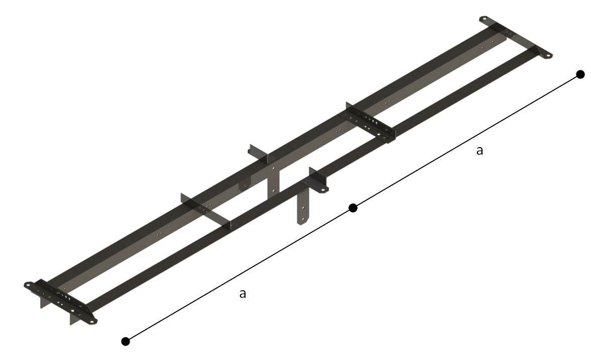
| Designation | Admissible vertical stress (daN) | Separation between adjacent phases or to the “a” mast axis (mm) |
|---|---|---|
| RH 1-15/14A | 250 | 1.5 |
| RH 1-20/14A | 250 | 2 |
| RH 2-15/14A | 450 | 1.5 |
| RH 2-20/14A | 450 | 2 |
Meaning of the initials making up the designation:
RH: Straight cross-bar for concrete and sheet metal posts.
1or 2: Identifies the load to be supported by the cross-bar or semi cross-bar, 250 or 450 daN respectively.
14A: Corresponds to the maximum distance, expressed in cm, of separation between beams de la cross-bar in accordance with the post geometry, type and nominal stress, sheet metal posts from 400 to 1600 daN and concrete posts (HV) from 400 to 1000 daN.
| Cross-bar | Load cases | Workloads + overload daN V | Workloads + overload daN L | Workloads + overload daN F | Factors of safety | Specified limit load Test loads daN V | Specified limit load Test loads daN L | Specified limit load Test loads daN F | Duration S |
|---|---|---|---|---|---|---|---|---|---|
| RH 1 | A | 250 | – | 533 | 1.5 | 375 | – | 800 | 60 |
| RH 1 | B | 250 | 225 | – | 1.5 | 375 | 338 | – | 60 |
| RH 2 | A | 450 | – | 533 | 1.5 | 675 | – | 800 | 60 |
| RH 2 | B | 450 | 225 | – | 1.5 | 675 | 338 | – | 60 |
V: Vertical load.
L: Load in the direction of the line.
F: Load transversal to the direction of the line.